Bas relief style CNC milling with an STL
So, we have these pieces that need a certain texture placed on them. Well, less a texture and more a 3D scanned surface of some sort of machine block or something. I’m not entirely sure of the application. All I know is that it requires a very fine surface to be milled so that it matches up with some sort of casting in order to grab it.
Anyways, were supplied with something like this, some much larger (this one’s 15″x5.5″):
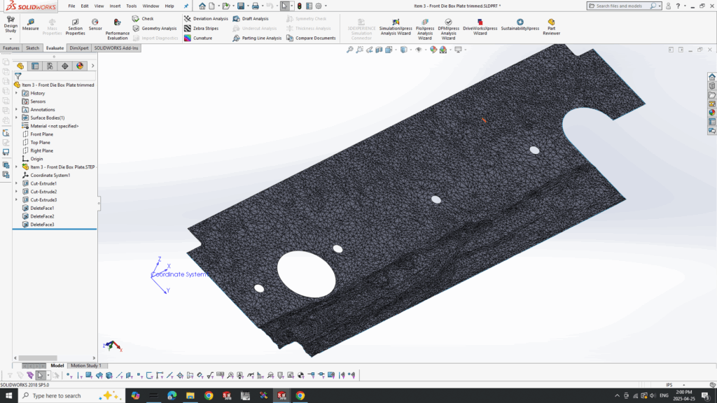
That’s the trimmed up version before I export it. So what I wanted to do was have the surface be milled in a square spiral, basically so that it is always climb milling but that the output is linear, not some weird arc. MasterCAM has a variety of options for surfacing but nothing quite like that. I could have it zig-zag but I didn’t want that.
So, I just programmed my own generator in python. It worked out OK. These are the steps:
- Load the STL file and find its X,Y and Z bounds
- Generate a grid based on the bounds at a resolution of the supplied stepover.
- Add a given number of grid lines to the outside, to give a bit of overlap
- Generate a spiral path with the points
- Scan each point on the grid with the Moller-Trumbore intersection aglorithm, a way to check the intersection of a ray to a triangle in 3D space. Perfect for STL since it’s all triangles.
- Any point that does not have a collision, mark as a non cut
- While scanning, use multiple ray intersections along the ball in order to account for the shape of the ball-nose end mill. (more resolution on the ball==slower)
- Output G-code based on these intersections
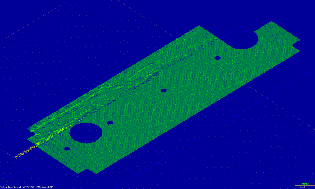
That is the DXF of the output. Works well.
If anyone wants it, they can have it. Enjoy. Also, in case you’re curous to see what it turned out like, here it is. I had to finish it with Mastercam surface routines though but the roughing (done with my program) was pretty good especially after filtering.
| Posted in Design, Machining, Programming | Comments Off on Bas relief style CNC milling with an STL