Bas relief style CNC milling with an STL
So, we have these pieces that need a certain texture placed on them. Well, less a texture and more a 3D scanned surface of some sort of machine block or something. I’m not entirely sure of the application. All I know is that it requires a very fine surface to be milled so that it matches up with some sort of casting in order to grab it.
Anyways, were supplied with something like this, some much larger (this one’s 15″x5.5″):
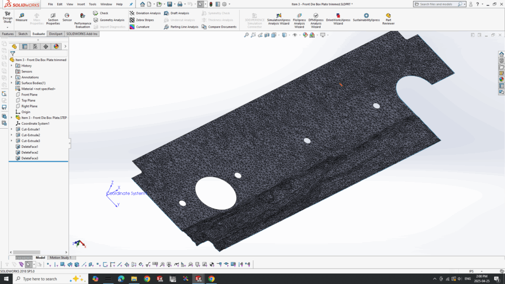
That’s the trimmed up version before I export it. So what I wanted to do was have the surface be milled in a square spiral, basically so that it is always climb milling but that the output is linear, not some weird arc. MasterCAM has a variety of options for surfacing but nothing quite like that. I could have it zig-zag but I didn’t want that.
So, I just programmed my own generator in python. It worked out OK. These are the steps:
- Load the STL file and find its X,Y and Z bounds
- Generate a grid based on the bounds at a resolution of the supplied stepover.
- Add a given number of grid lines to the outside, to give a bit of overlap
- Generate a spiral path with the points
- Scan each point on the grid with the Moller-Trumbore intersection aglorithm, a way to check the intersection of a ray to a triangle in 3D space. Perfect for STL since it’s all triangles.
- Any point that does not have a collision, mark as a non cut
- While scanning, use multiple ray intersections along the ball in order to account for the shape of the ball-nose end mill. (more resolution on the ball==slower)
- Output G-code based on these intersections
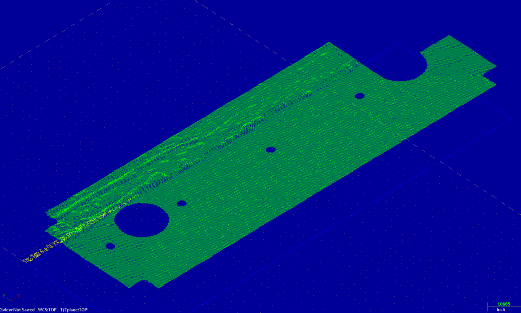
That is the DXF of the output. Works well.
If anyone wants it, they can have it. Enjoy. Also, in case you’re curous to see what it turned out like, here it is. I had to finish it with Mastercam surface routines though but the roughing (done with my program) was pretty good especially after filtering.
Spline Cutting Macro (HAAS Macro)
Wrote a quick spline cutting routine for cutting splines for the side. Supports starting at a given tooth, roughing depth, taper adjustment and finish depths. Can come from -/+Y and go any direction on X. Nothing too spectacular but I leave it here for fun.
%
O2023 (SPLINE CUTTING PROGRAM)
(STEVEN MACKAAY 2025)
(!!!USE AT YOUR OWN RISK!!!)

(SETUP VARIABLES)
#100 = 38.   (TOTAL NUMBER OF TEETH/SPLINES)
#101 = -.5   (START X POSITION)
#102 = 4.13   (END X POSITION)
#103 = -2.55   (CLEARANCE Y POSITION - ABSOLUTE DISTANCE FROM Y0)
#104 = -2.35  (START Y POSITION - ABSOLUTE DISTANCE FROM Y0)
#105 = -2.2323   (FINISH Y POSITION - ABSOLUTE DISTANCE FROM Y0)
#106 = 0.02  (Y STEPDOWN AMOUNT - POSITIVE VALUE)
#107 = 0.001  (Y FINISH PASS AMOUNT - POSITIVE VALUE)
#108 = 1.25 (CUTTER RADIUS - POSITIVE VALUE)
#109 = 0.002 (TAPER AMOUNT Y PER UNIT X - POSITIVE TAPER WIDENS AWAY FROM X AXIS AT ENDX)
#110 = 15.  (CUTTING FEEDRATE F)
#111 = 5.0   (PLUNGE FEEDRATE F)
#112 = 50.0  (CLEARANCE FEEDRATE F)
#113 = 460  (SPINDLE SPEED S)
#114 = 1.0   (START TOOTH NUMBER 1 TO #100)
#115 = 4.0   (SPINDLE DIRECTION 3 FOR M03 CW, 4 FOR M04 CCW)

(CALCULATED VARIABLES)
#120 = 0 (CURRENT TOOTH NUMBER)
#121 = 0 (ANGLE FOR CURRENT TOOTH)
#122 = 0 (CURRENT Y POSITION FOR STEPDOWN)
#123 = 0 (CUTTER COMPENSATION - WILL BE POSITIVE OR NEGATIVE BASED ON Y SIGN)
#124 = 0 (DIRECTION FLAG - 1 FOR POSITIVE Y, -1 FOR NEGATIVE Y)
#125 = 0 (TOTAL NUMBER OF STEPDOWNS)
#126 = 0 (CURRENT STEPDOWN NUMBER)
#127 = 0 (STEP DIRECTION - SIGN OF STEP TOWARDS Y0)
#128 = 0 (FINISH PASS Y POSITION)
#130 = 0 (REMAINING DISTANCE AFTER FULL STEPDOWNS)

(DETERMINE APPROACH DIRECTION)
IF [[#103 LT 0]] THEN #124 = -1 (APPROACHING FROM NEGATIVE Y)
IF [[#103 GT 0]] THEN #124 = 1 (APPROACHING FROM POSITIVE Y)

(DETERMINE STEP DIRECTION - TOWARDS Y0)
#127 = -#124 (STEP DIRECTION TOWARDS Y0)

(CALCULATE CUTTER COMPENSATION)
IF [[#124 LT 0]] THEN #123 = -#108 (NEGATIVE Y - SUBTRACT CUTTER RADIUS)
IF [[#124 GT 0]] THEN #123 = #108 (POSITIVE Y - ADD CUTTER RADIUS)

(CALCULATE FINISH PASS Y POSITION)
#128 = #105 - #127 * #107 (POSITION BEFORE FINISH PASS)

(CALCULATE NUMBER OF STEPDOWNS)
#125 = FIX[ABS[#104 - #128] / #106] (NUMBER OF FULL STEPDOWNS)
#130 = ABS[#104 - #128] - [#125 * #106] (REMAINING DISTANCE AFTER FULL STEPDOWNS)
IF [[#130 GT 0.0001]] THEN #125 = #125 + 1 (ADD ONE MORE STEPDOWN IF NEEDED)

G90 (ABSOLUTE POSITIONING)
G17 (XY PLANE SELECTION)
G20 (INCH PROGRAMMING)
G40 (CANCEL CUTTER COMPENSATION)
G49 (CANCEL TOOL LENGTH COMPENSATION)
G80 (CANCEL CANNED CYCLES)
T15 M6 (SELECT TOOL 15)
G43 H15 (APPLY TOOL LENGTH COMPENSATION)
S#113 (SET SPINDLE SPEED)

(MAIN LOOP FOR EACH TOOTH)
#120 = #114 (START AT SPECIFIED TOOTH)

M08 (COOLANT ON)

WHILE [[#120 LE #100]] DO1
  (CALCULATE TOOTH ANGLE)
  #121 = 360.0 * [#120 - 1] / #100 (ANGLE FOR CURRENT TOOTH)

  (POSITION TO TOOTH START)
  G0 A#121 (ROTATE TO TOOTH ANGLE)
  G0 X#101 Y[#103 + #123] (RAPID TO START POSITION WITH CLEARANCE Y AND CUTTER COMPENSATION)

  (START SPINDLE AND COOLANT)
  IF [[#115 EQ 3]] THEN M03
  IF [[#115 EQ 4]] THEN M04


  (RAPID TO Z0)
  G0 Z0

  (MOVE TO START Y POSITION)
  G1 Y[#104 + #123] F#112 (FEED TO START Y WITH CLEARANCE FEED AND CUTTER COMPENSATION)

  (STEPDOWN LOOP)
  #126 = 1 (INITIALIZE STEPDOWN COUNTER)

  WHILE [[#126 LE #125]] DO2
    (CALCULATE CURRENT Y STEPDOWN)
    IF [[#126 LT #125]] THEN #122 = #104 + #127 * #106 * #126 (INCREMENTAL STEPDOWNS TOWARDS Y0)
    IF [[#126 EQ #125]] THEN #122 = #128 (LAST STEPDOWN BEFORE FINISH PASS)

    (PLUNGE TO STEPDOWN)
    G1 Y[#122 + #123] F#111 (PLUNGE TO CURRENT DEPTH WITH PLUNGE FEED AND CUTTER COMPENSATION)

    (CUT TO END X WITH TAPER)
    G1 X#102 Y[#122 + #123 + [#109 * #124]] F#110 (CUT TO END X WITH TAPER ADJUSTMENT)

    (RETRACT TO CLEARANCE)
    G0 Y[#103 + #123] (RAPID BACK TO CLEARANCE Y WITH CUTTER COMPENSATION)

    (RETURN TO START X)
    G0 X#101 (RAPID BACK TO START X)

    (INCREMENT STEPDOWN COUNTER)
    #126 = #126 + 1
  END2

  (FINISH PASS)
  G0 Y[#103 + #123] (RAPID TO CLEARANCE Y)
  G0 X#101 (RAPID TO START X)
  G1 Y[#105 + #123] F#111 (PLUNGE TO FINISH Y WITH PLUNGE FEED)
  G1 X#102 Y[#105 + #123 + [#109 * #124]] F#110 (CUT FINISH PASS TO END X WITH TAPER)
  G0 Y[#103 + #123] (RAPID BACK TO CLEARANCE Y)

  (INCREMENT TOOTH COUNTER)
  #120 = #120 + 1
END1

(PROGRAM END)
M5 (SPINDLE STOP)
M9 (COOLANT OFF)
G28 G91 Z0 (RETURN TO Z HOME)
G28 G91 Y0 (RETURN TO Y HOME)
M30 (END PROGRAM)
%| Posted in Machining, Programming | Comments Off on Spline Cutting Macro (HAAS Macro)
Still selling, Comparators!
Back in 2018 I designed a type of comparator (and setting master) for compressor valve grooves. Just finished another batch of 10 of them, it went well. Nowadays we wrap the master in paper along with oil in order to prevent rusting. Sending them to the southern states made them rust a fair amount.
Just leaving this here for posterity.
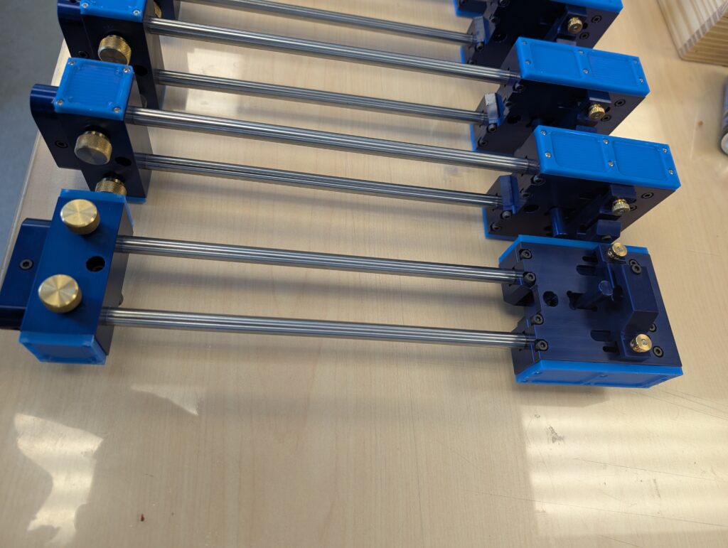
They are a pain in the ass to align well though, I am going to do a mild redesign on the next set. I always say that but we always need them yesterday.
| Posted in Design, Machining | Comments Off on Still selling, Comparators!
NCComm – An RS232 device for CNC communication
![]()
So, I wanted to try my hand at making a communication device between a standalone device and the CNC, something I wanted. I achieved that. I wanted it made out of the most common parts an average person can easily buy off Aliexpress. You can buy one for like 200 bucks but it was fun to make nonetheless. Things you need for this build:
- Arduino Mega 2560 or 1280 (I used this because it had enough IO, you could use a nano or a standard arduino but you’d wanna use a different keypad)
- A membrane keypad (This one is a 4×5 keypad, so 9 IO are needed)
- An SD card module that accepts 5v. (I used the large style, it is more hardy in an industrial environment.)
- A 2004 LCD module with an I2C backpack (You can use a standard LCD without a backpack but you’ll want to change the way the output is used, I made a wrapper for that.)
- An RS232 module. (This one should be with RTS and CTS, most CNC’s I know of need handshaking or just a CTS signal unless you tie the RTS CTS lines together on the cable)
- Not necessary but I used a hat for the 2560 just to simplify the connections to the board to use standard headers.
Simple, straightforward. Here is the code I have thus far. It’s not too solid and handshaking isn;t working perfect but it works thus far.
Here: https://www.smackaay.com/wp-content/uploads/2025/04/NCComm.zip
Enjoy
| Posted in Electronics, Machining, Programming | Comments Off on NCComm – An RS232 device for CNC communication
Gage Block Buildup Calculator
So, I have that Python source code on the side of my site there for calculating gage block buildups. I figured it was time to turn it into a JS program so that people can just access it from the web. Not super complicated but useful nonetheless.
http://smackaay.com/files/gbcalc/gbcalc.html
Features as follows:
- Imperial 81, 28, 34, 36 and 92 pc sets
- Metric 88, 47 and 112 pc sets
- Multiple ( as many as you want) results
- The ability to remove blocks from the list if they are either missing or used in a previous buildup. This is handy.
Anyways, hope somebody out there enjoys this!
| Posted in Machining, Programming | Comments Off on Gage Block Buildup Calculator
An RTJ chart
Here is a chart for RTJ ring groove facings. It’s very specific to my own use case but maybe somebody else will find it useful. I guarantee nothing, if you use it, it’s at your own risk. Bottom width is the size at the bottom of the groove, Largest Ball is the largest ball that will sit tangent at the top of the groove, and well, Smallest is the one that will sit on the bottom and touch the two sides. Obviously you want to be somewhere between, not at, theses sizes. Also, the lists on the bottom denote the Depth, Width sets and the numbers that follow are the R sizes that match that set.
04.27.24CMM, a test video
So, I was measuring a plate on our Mitutoyo CMM yesterday and I figured it’d be a good test to see how videos embed on WordPress these days. When I started this site the first time, you could not embed videos very easily and you had to embed with either YouTube or whatever other video service was available. Still, the limit is only 512MB but, hey, good enough. That’s almost enough for a movie.
This was a plate we needed to grind flat withing a few thou. Worked out well.
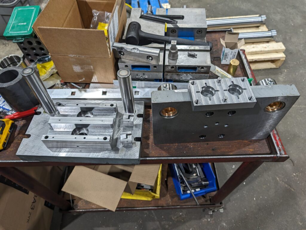
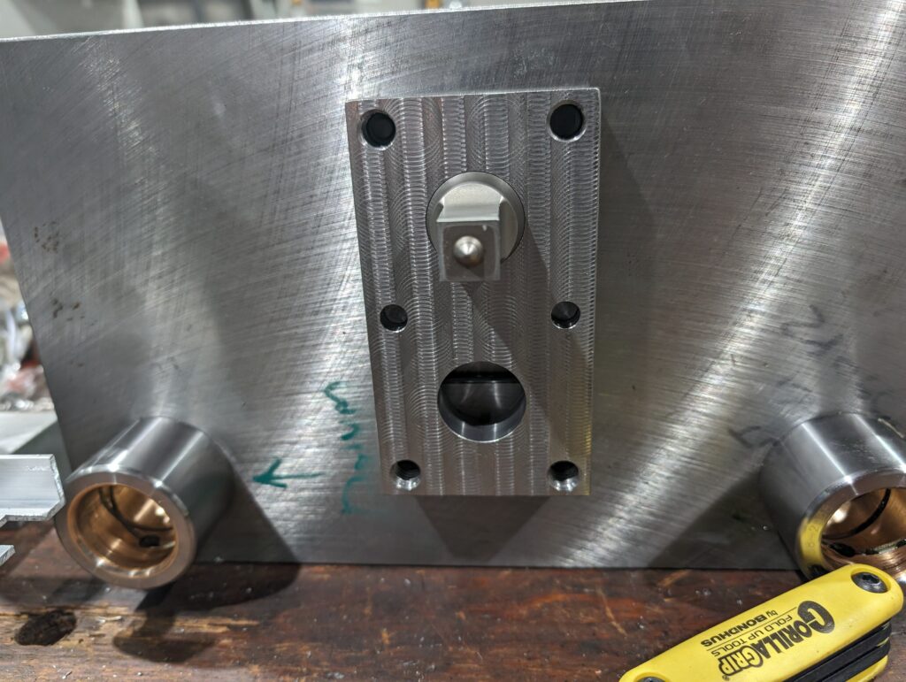
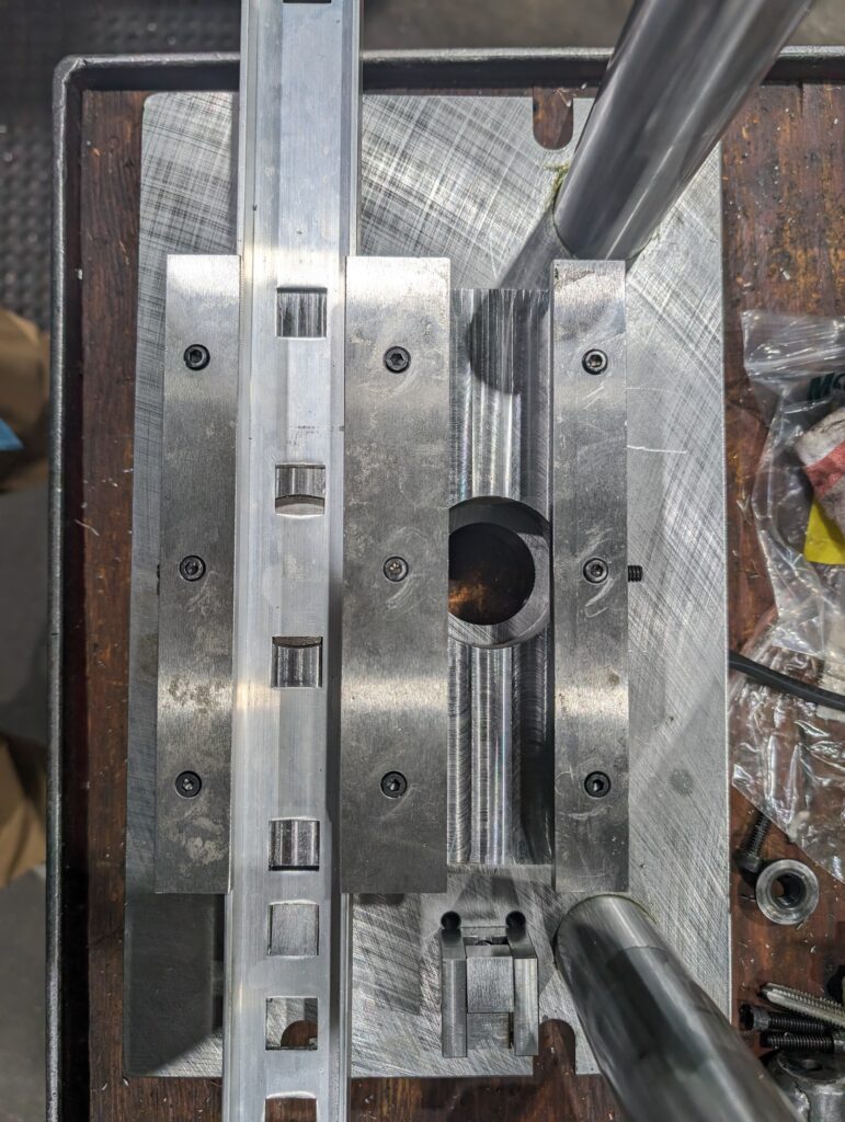
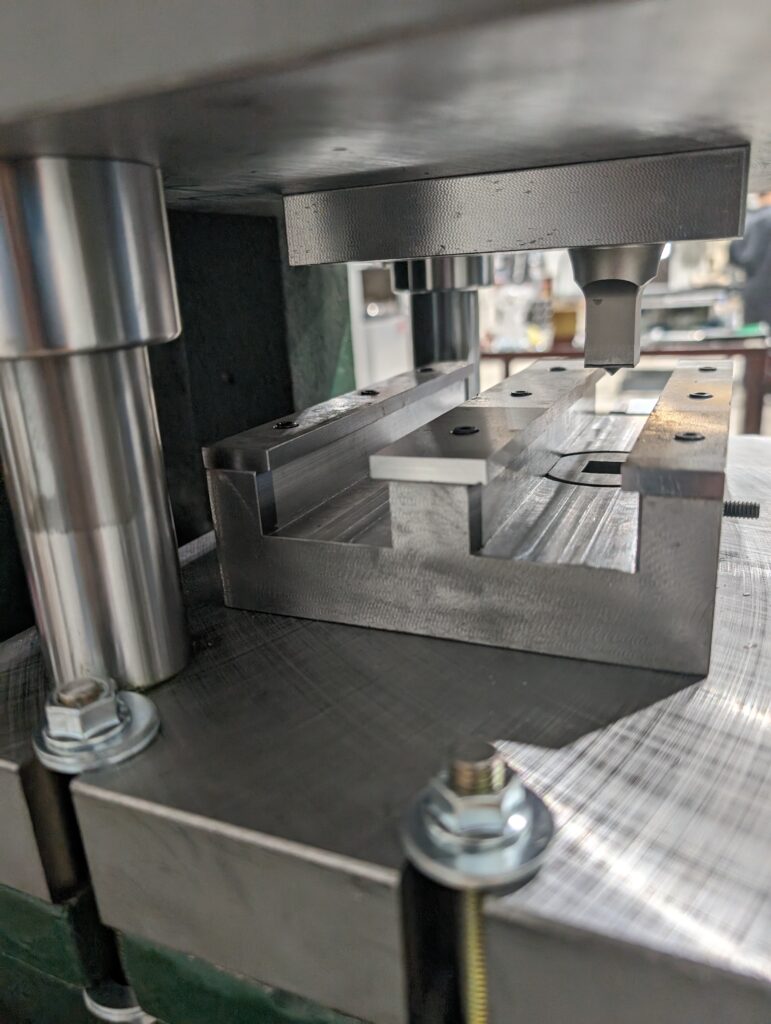
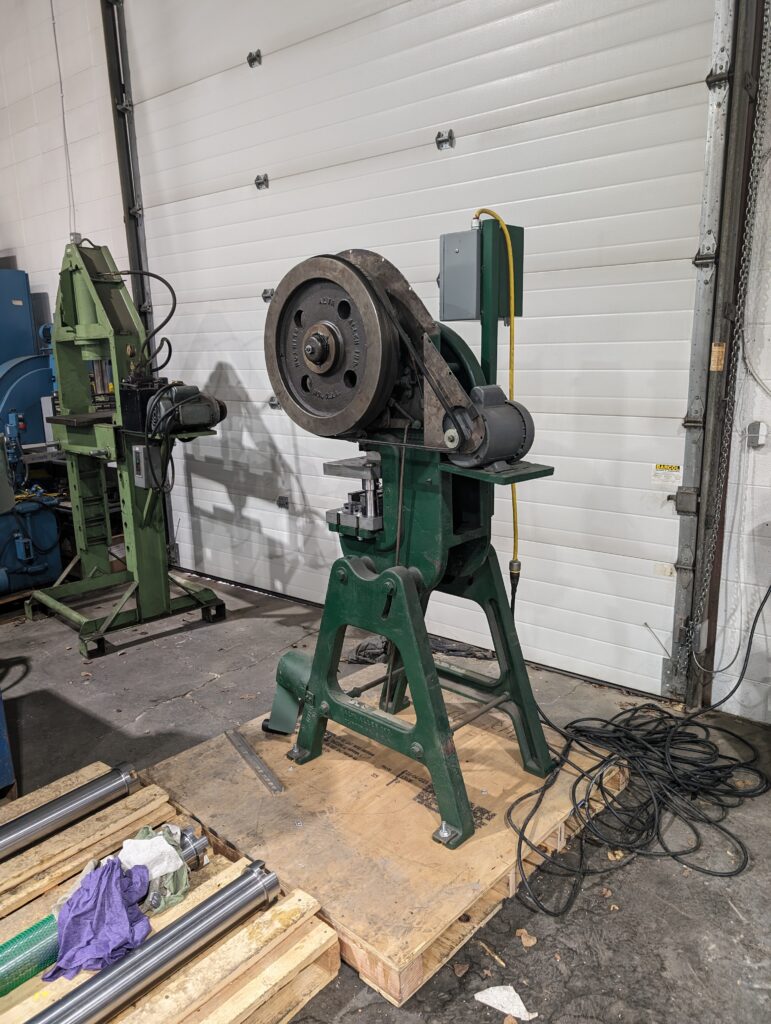
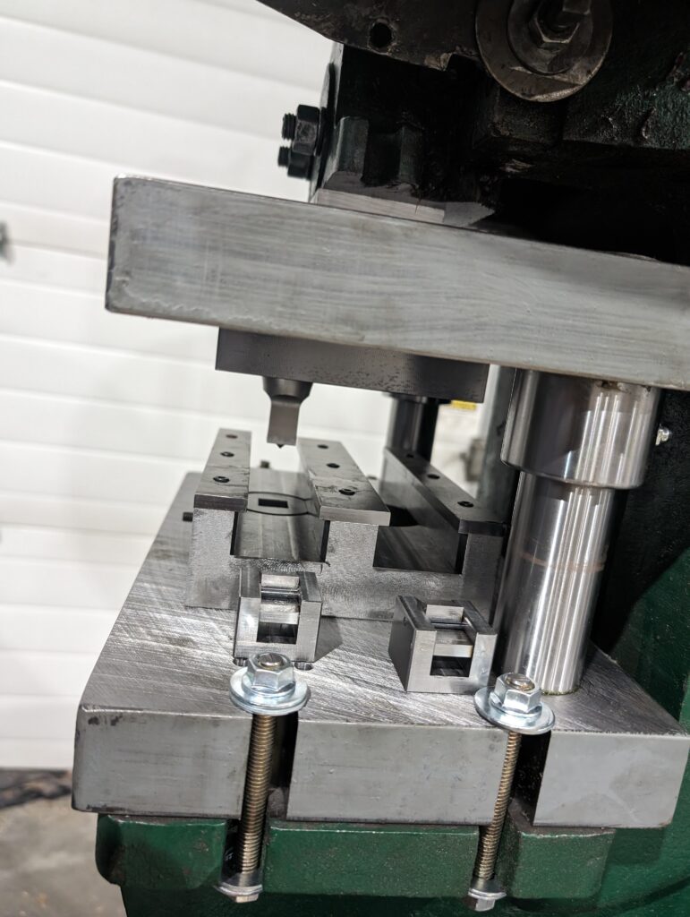
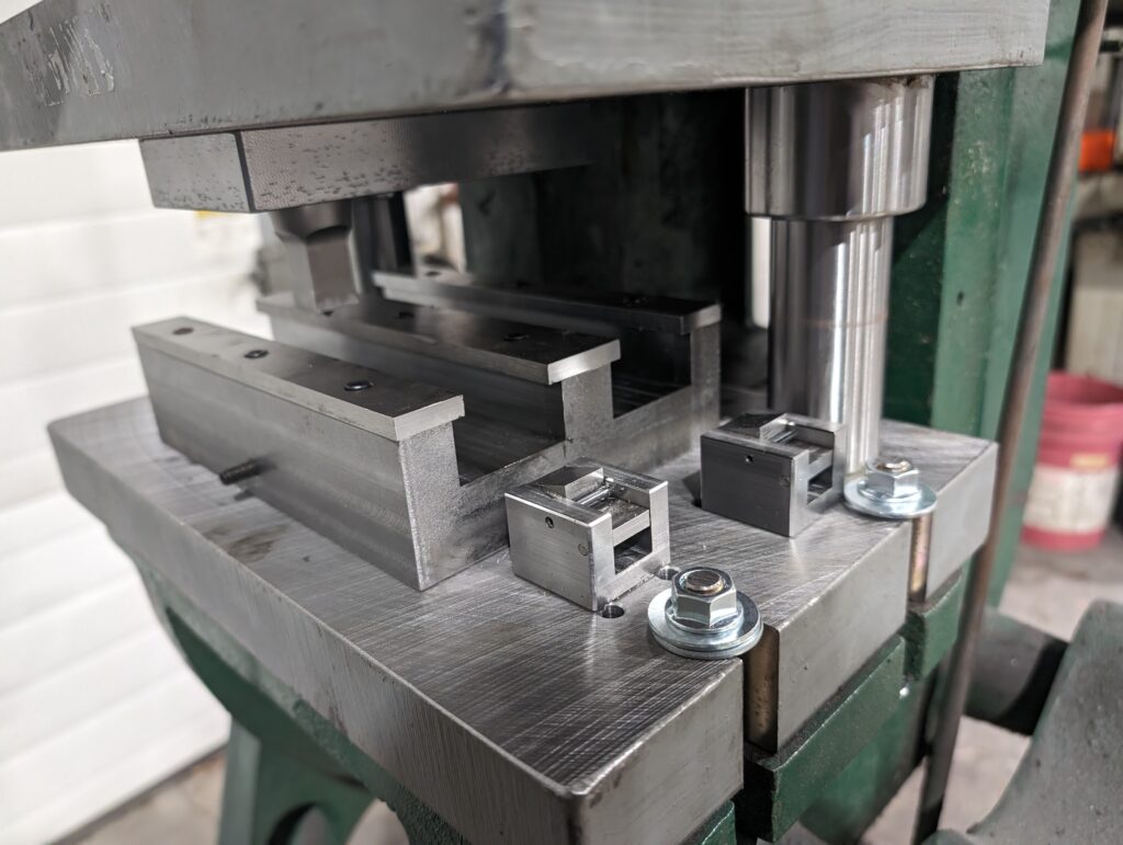
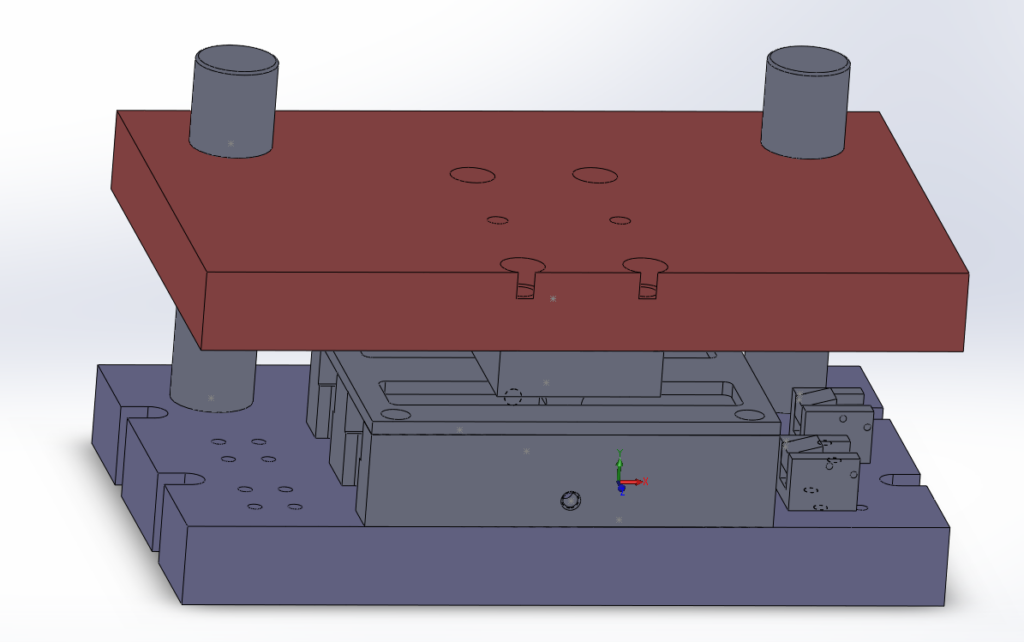
04.25.24A new die/punch housing
Just finished a new die/punch housing for use on an old press. Works well and allows you to index at different distances. The initial drawing was kind of wrong when I drew it but I just shifted it a bit to work given the machine.
| Posted in Design, Machining, Programming | Comments Off on Bas relief style CNC milling with an STL