So, I’ve added a gallery feature to the site, a piwigo one. Seems to work just fine Go here http://smackaay.com/gallery/
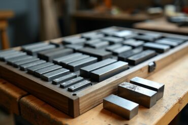
Anvil Micrometers for Rotor measurement
Well, we just made 5 rotor measurement micrometers, the most we’ve seen in a batch thus far. Figured I’d share since they were interesting to…
Mr. BarFace – Generate facing toolpath for round stock
So, I wrote a program, out of some necessity for speed to allow the rough facing of the side of a bar of round stock….
CalculonX – A console calculator
So, I’ve been using a console calculator that I made for over 20 years ago so I’ve decided to update it and basically just make…
Image Geotagger
Here is an image geotagger. It uses leaflet for the map so it may give you guff depending on your browser security settings. Click HERE!
A quick trip to Wildwood AB
Went to go visit family friends in Wildwood Alberta. Nice little town, wouldn’t mind retiring there.
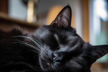
Photo Comparisons P5000, 6000, zs99, TG-2 and HP735
So, I decided to do a little test and compare a small variety of my PS cameras, those being the Panasonic ZS99, the Nikon P5000…
A web based image labeller
So, I needed something to label images with EXIF data for easy comparison. This will allow you to apply labels based on data from the…
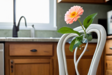
New ZS99 camera, gettin’ out
Been getting the itch to take some photos again, capture things as they are. Regular boring scenes that we may look upon as just little…
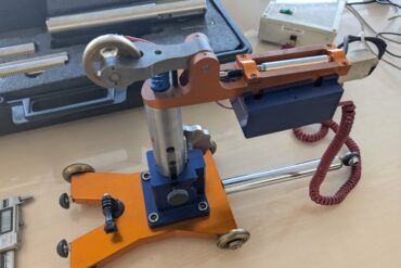
A Final Comparator
Over the years I’ve designed a whole range of different comparators for various purposes and with various external constraints. I just finished my hopefully final…
Bas relief style CNC milling with an STL
So, we have these pieces that need a certain texture placed on them. Well, less a texture and more a 3D scanned surface of some…
Spline Cutting Macro (HAAS Macro)
Wrote a quick spline cutting routine for cutting splines for the side. Supports starting at a given tooth, roughing depth, taper adjustment and finish depths….
Still selling, Comparators!
Back in 2018 I designed a type of comparator (and setting master) for compressor valve grooves. Just finished another batch of 10 of them, it…
NCComm – An RS232 device for CNC communication
So, I wanted to try my hand at making a communication device between a standalone device and the CNC, something I wanted. I achieved that….
DooM WAD Level Selector
I was going through old CDs and came across some doom wads, levels for the old DooM. So I fired up GZdoom and tried a…
Texture Generator and Claude 3.7 Sonnet
So, I was at the mall, waiting, and I was thinking about the old Wolfenstein 3D. I was thinking about the textures and wondering if…
Ripping an image based PDF to text (and old TurboBASIC commands)
Recently, I wanted to pull text from a PDF that was scanned in from an old manual, namely the Borland Turbo Basic manual. The text…
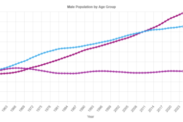
Demographic charts
So, I’m pretty interested in the state of the world and how populations in wealthier countries are starting to fall. I was kind of looking…
New prompt permutation script
A while back I made a prompt permutation script for generating large numbers of image prompts for use in automatic1111. I updated it with a…
Gage Block Buildup Calculator
So, I have that Python source code on the side of my site there for calculating gage block buildups. I figured it was time to…
The YouTube Recycle Bin
I was watching a video from a youtuber KVN AUST. The video: https://youtu.be/8uHFm6LK6PE?si=SLIaCEzNBx_iL97V It featured a map for looking at and searching for odd videos…
A visit from an old friend, the boreGauge
A few years back we made a gauge for measuring large bores in hydraulic cylinders. Seems the company that bought it from us needed the…
StableDiffusion Permutation Script Update
So, like a week ago I wrote a script to make permutations for SD prompts. I’ve updated the script to allow for random terms as…
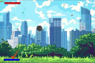
Pong-2024
I was bored and made a quick Pong game. It’s not great, not terribly well finished but I wanted to see how good the tools…
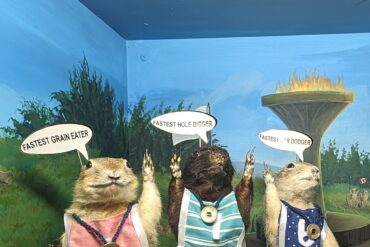
Calgary Zoo and Torrington Gopher Museum
Last weekend we decided to go with my parents for a quick trip to our neighbors to the south and visit the Calgary Zoo, It…
Resolutions for SD image generation
When making images for StableDiffusion it’s best to take the aspect ratio in mind and make it fit into the total number of pixels that…
A quick script for creating prompt permutations for StableDiffusion
So, I enjoy making stuff in StableDiffusion and in the WebUI interface is an option for a prompt list. I like using the Prompt S/R…
Some of my AI ‘art’
I’m not stupid enough to consider plugging in some prompts to a diffusion AI to be art but I enjoy it nonetheless. Also, I’m aware…
An RTJ chart
Here is a chart for RTJ ring groove facings. It’s very specific to my own use case but maybe somebody else will find it useful….