Viscometer Report – Aug 6 2008
Since the last report done on the viscometer, a great many things have changed in regards to the mechanical and electrical design of the unit. It is now a rotary viscometer instead of a paddle based unit. It operates in a similar fashion to the typical Stormer viscometers in that it measures the energy required to push a paddle at 200 (or other specified) RPM; the greater the force required, the larger the KU value.
Summary of what’s been done so far
So far, the majority of the unit is in a functional state. Recent modifications have allowed the unit to function in a more reliable fashion. The unit works on the following principle:
- There is a gear motor that is specified to run at 275RPM at full power.
- The motor’s shaft is fitted with an encoder.
- The motor is started and operated with a PWM (Pulse Width Modulation) output.
- If the motor is running too fast (>200RPM) , the duty cycle is dropped.
- If the motor is running too slow (<200RPM) , the duty cycle is increased.
- From the duty cycle values sampled over a period of time is derived a viscosity value, preferably translated into Krebs units.
So far, things that are done/workable are:
- Main CPU w/o calibration and safety routines
- Tach Controller
- PWM Controller
- High ESD Input controller
- Auxillary controller (not implemented yet)
- Motor controller
- Main Viscometer Unit
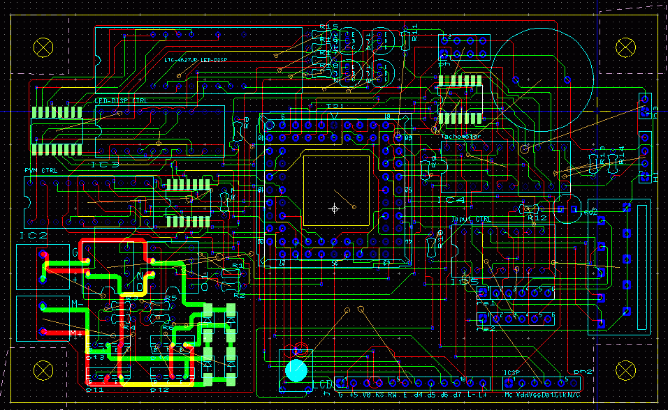
Here is an image detailing some of the items on electronic side of the viscometer:
Click to enlarge
Whats going on now?
Currently, I’m working on a few items related to the viscometer, namely:
- Viscosity testing with mostly a flour-water mix since the resulting mixture is similar to the shear thinning fluids of paints and coatings.
- Explosion proof case acquisition. While there are a great many NEMA-7 Enclosures available, I’m trying to find one that isn’t $800+ per case.
- Algorithm changes. Since the samples that come into the unit are not as clean as they appear on the screen, the sampling algorithm has to be tested in order to produce accurate and useful data to the automation system.
- RS-232 Output device. I’m currently working on the output portion of the device, that way the automation system can read what’s being measured.
- New Mainboard
This board integrates everything that you see in the picture above and allows it to take on the same footprint as the 5×3 power supply. This allows one to purchase smaller enclosures and it’ll be a lot more reliable with fewer interconnects.
Some Problems
While there aren’t any showstopping problems, there are a couple of kinks to work out.
- With the increased friction from the new top and bottom bushings, the sensitivity to the lower end of the scale (around water’s viscosity) is almost Nil. I’m going to play around with the sizes and try a couple of tricks in the way of selectively modifing the outgoing voltage. The bushings are a double-edged sword, they help remove the reliance on the alignment of the shaft and the unit in general but, of course the aforementioned friction is now a problem.
- Long warm up times. In order to reach a stable set of samples with any fluid, the unit must be on for at least 5 minutes. This has been exacerbated by the bronze bushings to about 7 minutes. I suspect this isn’t the fault of the motor but of the seals and lubricant needing a warm up time in order to drop their friction levels. I am looking at different lubricants and at adding a start up routine that runs the motor at full speed for 40 seconds or so, this seems to mitigate the issue.
- Still some measurement differences based on vertical or horizontal alignment….
Well I hope this was informative, if you have anything you want to ask, feel free to do so.


 The Amp Hour Radio Show